Convert Shell To Sheet Metal

Solidworks Solid To Sheet Metal Tutorial Convert To Sheet Metal Convert Shell To Sheet Metal Youtube

Solidworks Convert To Sheet Metal Cylinder Youtube

Inventor Sheet Metal Converting Solid Models Youtube
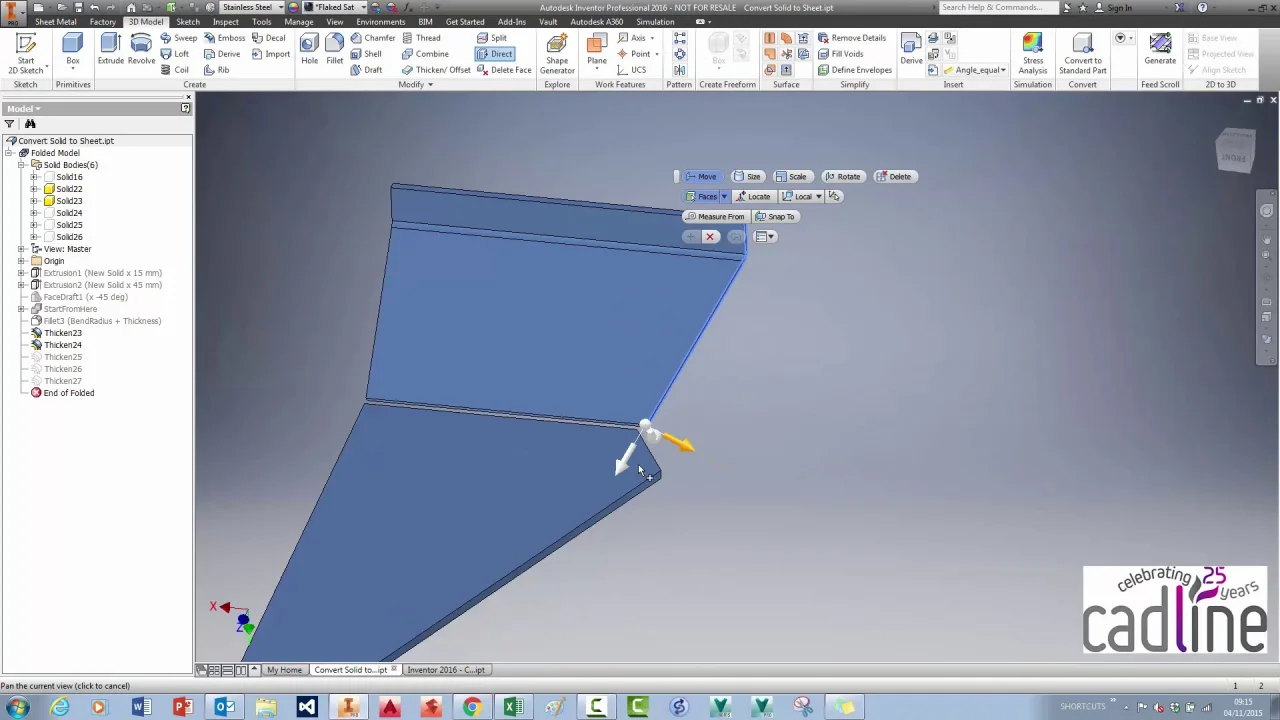
Inventor 2016 Converting A Solid To Sheet Metal An Alternative Method Cadline Community
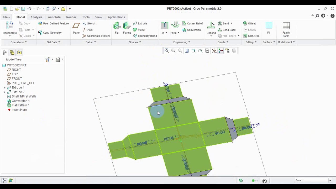
Solid To Sheet Metal Conversion In Creo 2 0 Youtube

Nx Sheetmetal Convert To Sheet Metal Flat Solid Hindi Urdu Youtube

If you don t have the sheet metal tab open right click in the area where the 1 arrow points then click sheet metal.
Convert shell to sheet metal.

How Can I Convert This To Sheet Metal So That I Can Add Flanges And Flatten It Sheet Metal Canning Metal
Http Files Goengineer Com Docs Support Sheet 20metal 20bodies Pdf

How To Convert 3d Part Into Sheet Metal In Solidworks Youtube

How To Convert To Sheet Metal In Solidworks
Source : pinterest.com
